
This is the new technology for converting wind energy into electrical / mechanical energy emerged as a result of researches of the Vortex-type air flow concentrator (International application for invention PCT/IB2017/054185 from July 12, 2017 priority date June 20, 2017, under patent RU 2655422 C1 registered and published on May 28, 2018). Similar studies of air flows inside a concentrator have not been conducted before.
Anyone can freely download the wind directing element template (of single curvature) of the vortex concentrator from the project page on Facebook or LinkedIn and build (non-commercial use only) a small charging station for their gadgets or a deflector to be installed over a vent or chimney on the roof.
The coefficient of wind energy use determined during these studies, at certain ratios of the height of the vortex concentrator to the diameter of its working zone (these ratios are in the range of 1.4-1.5), achieved up to 50%. At the same time the wind directing elements of the tested models of the vortex concentrator and turbine blades made of cellular polystyrene did not have an aerodynamic profile, and the geometry of the turbine blades was not quite ideal.
The research results formed the basis of the new technology and of the new design of a megawatt-class industrial wind power plant (see one of the solutions in Fig. 1, press the button below):
1. Vortex-type air flow concentrator covered by a domed roof and equipped with lightning conductors, consists of identical wind directing elements (in the given version there are six of them) made of metal structures covered by sheets of glass-reinforced plastic and having an aerodynamic profile (for example, materials of blades of the modern wind turbines that have served their term can be used, that will solve a problem of their recycling);
2. Supporting structures, including the concrete or pile foundation and supports made of prestressed concrete, serve as the basis for the vortex concentrator and steel beams, which fix the shaft of the turbine rotor in the bearing units from longitudinal and lateral shifts. The height of the supports for the wind power plants of more than 100 kW of installed capacity should be at least 20 m (~20-30% of the total height) to ensure the removal of slower flows behind the wind turbine to prevent the occurrence of back pressure;
3. The turbine consisting of rods with blades at the ends and a hub with a control system (disk in the center), which is responsible for turning the rods to change the pitch angle, and for moving the rods -in and -out the hub (International application for invention PCT/IB2019/057055 from August 21, 2019 priority date July 21, 2019, under patent RU 2718594 C1 registered and published on April 08, 2020);
4. Generator room (the dome-shaped building in the base) including the building itself, the generator with the CVT (continuously variable transmission), electric equipment and controller with the operator's control panel.
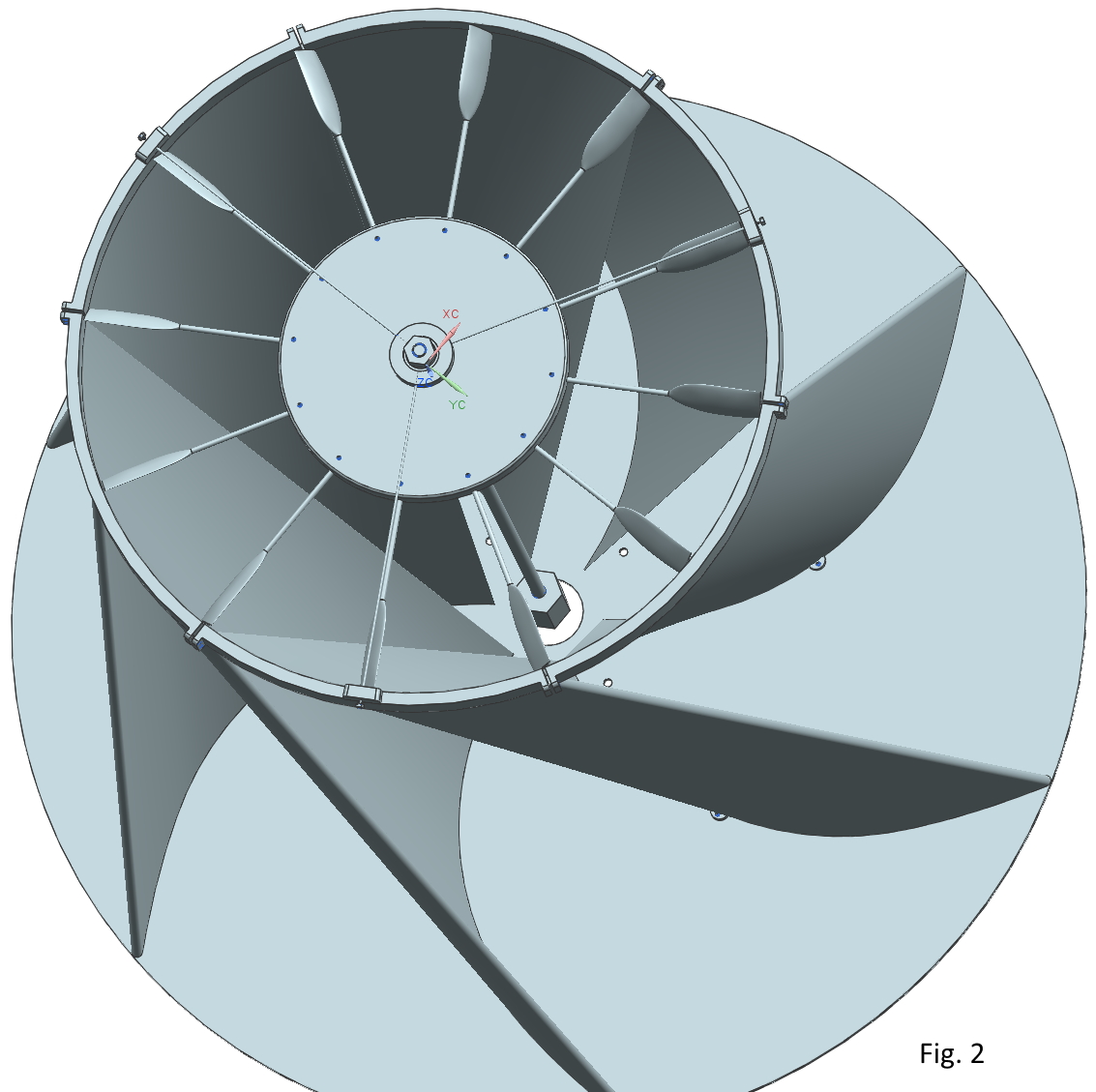
For a private use, instance for power supply of a country house, farm or electric vehicle charging stations, the wind power plant could be significantly simplified. The vortex air flow concentrator could act as a supporting structure. In the wind power plants of up to 15-20 meters height, the air flow vortex concentrator can be turned over so that the working zone and the turbine are on the top, and its wind directing elements serve as supports for the turbine. The vortex concentrator for itself could find its application also in other areas, for example, in a buildings ventilation system. In Fig. 2 you can see the assembly of the wind turbine for charging gadgets, and in Fig. 3 part of the semi-automatic blade control system.
The introduction of this technology will allow wind power to grow from a subsidized industry into a profitable component of the world's electricity production. It will be possible to use previously not promising regions in terms of wind energy. Changing the main principle in the wind power from maximum generation per year to stable power generation in a wide range of wind speeds will reduce the need to accumulate excess electricity generation and simplify the coordination of generation with the power grid of the regions.
The main problems of modern wind turbines (those with horizontal axis types) that inhibit the development of wind power engineering and which are solved by a new type of wind power plant:
Inefficiency of modern wind power plants in gusty wind and / or with a rapid change in wind direction.
Narrow operating range of wind speeds, high start-up speed and rated wind speed.
Complexity of maintenance (repair and replacement of worn parts of the wind power plant) due to the location of the main power components, yaw system, control systems etc. on a mast.
Design constraints of the installed capacity due to the location of the majority mass of the equipment (generator, multiplicator, yaw system, electrical equipment and turbine) on a mast.
Low profitability in the absence of government benefits and subsidies due to low Efficiency rated output (Capacity factor) and short lifetime (15-25 years) that also creates the problem of recycling.
Large exclusion zone around wind farms not only because of the noise but also because of scattering of the turbine fragments in case of destruction or of ice while icing over considerable distances.

High efficiency of the proposed wind power plant is provided by the airflow vortex concentrator (which does not require any yaw system) as well as by the turbine blades’ control system that is located in a hub in the center of the working zone (the disk in the base of the vortex concentrator) from where rods with blades at their ends move out radially. The vortex concentrator provides a spiral movement of the captured airflow to the turbine blades through the outer edge of the working zone. The width of the airflow is mere 20-25% of the working zone’s radius that is there is no any air movement in the center of the vortex concentrator like in the center of a hurricane. Therefore it is sufficient for the blades to have a length of no more than 20-25% of the radius of the working zone in order to use the energy of the air flows in full. Thus, the blade control system can completely or partially remove the blades from the influence of air flows.
The concentration of the airflow and the moment of force applied to the blades of the turbine provide a low start-up speed of the unit (up to 1 m/s).
The control system provides the turning of the blades to change pitch angle as well as the retracting of the rods for transformation the low-speed multi blade turbine in three-bladed turbine with high rotation speed or completely retracts all the rods to prevent breakage in a storm wind. All this extends the operating range of wind speed, and also reduces the wind load when wind speed increases up to 15-20 m/s or higher.
Due to the mass of the hub with the control system it is a flywheel with auto balancing system, smoothing the gusty wind and preventing low-frequency vibrations. This system ensures the smooth operation of the generator and reduces the wear of mechanical systems. The expected Efficiency rated output (Capacity factor) is 60-80% vs. 30-40% in the modern wind turbines, depending on wind power potential of the region.
Generator, CVT, electrical equipment and controller with operator’s control panel are at the bottom of the wind power plant, in a domed building, providing the easy access to the systems of the power plant and the absence of restrictions on the mass/capacity of the equipment.
The bearing structures of prestressed concrete provide the lifetime of the new wind power plant from 50 to 100 years and more.
The turbine’s location in the working zone of the vortex concentrator, surrounded on all sides by bearing elements of the structure, eliminates uncontrolled scattering of fragments of the blades in case of destruction, and of ice while icing. In addition, the external elements that surround the working zone shield from the noise produced by the turbine.
This design allows to scale the wind power plant. The Bearing structures can be initially built with the expectation of a larger height and power, with a larger diameter of the working zone. At the same time, a concentrator with a working zone made as an insert and a generator are initially installed designed for the less power, thereby reducing the initial investment of the wind farm. The design of the turbine with retractable rods with blades allows to adapt it to different diameters of the working zone. To increase the power of the wind power plant, it is enough to change only the concentrator with the working zone to larger ones and buy an additional generator, which is installed together with the first one.
MARKET
Almost 2 years ago, EU plans for wind power investments were announced. The EU's planned investment in wind energy will reach €239 billion (cumulative) by 2030.
And in May of 2019, the elections to the European Parliament showed the attitude of the electorate to the programs for clean energy and carbon free industry in Europe. «In the next 5 years EU funding must be targeted at projects that deliver on our commitments under the Paris Climate Agreement: that’s more funding for research and innovation in zero-carbon energy, starting with wind; and for electricity grids which we need to expand as we deliver the energy transition.»
The increase in wind power in the world for 2018 amounted to 50.1 GW. It is necessary to add power that are introduced annually instead of worn ones. This is the total potential annual market volume.
The royalty range for Renewable Energy Patents (Page 14) is 2-5%. The cost of construction per kW of installed capacity multiplied by the royalty rate in% and divided by 100% is taken as the cost of a unit of production. For modern industrial wind turbines the cost of construction per kW is over € 900 / kW (Page 33).
It is innovative technical solutions in the field of clean energy that will primarily get access to these EU funds. Consequently, wind turbine manufacturers will hunt for any developments in this area, since, if there is a new technology, the replacement of wind turbines that have expired or construction of new ones, using the old technology will become inexpedient. The company, the first to establish mass production by these technologies, will receive an absolute advantage in the market.
GOALS
1. To make a technological breakthrough in wind power by offering a new, more profitable and safer, more reliable wind power plant, which can be operated in regions that are called “poor” and “marginal” in modern wind power, as well as in regions with severe climatic conditions and to develop technological processes to establish serial production of new wind power plants.
2. To seek and develop new areas of this technology, for example, in building ventilation systems, as well as to develop areas related to wind power, for example, systems of accumulation of excess wind energy through the production and accumulation of various energy carriers (hydrogen, methane, etc.)
On the timeline below, it is convenient to monitor what has been done and what is yet to be done. In addition, the stages of solving certain tasks are disclosed in more detail. In particular, the essence of the invention is explained, the Formula of the Invention is given in the latest edition (modified under article 34 of the PCT procedure before the IPEA), various documents, the research program and links to information resources are placed.

